OSI Model (Open Standards Interconnection Model) was created by the International Organization for Standardization (ISO). With the technology boom came the rise of several giants in the fields of networking devices and software, including Huawei, Nokia, Cisco, Microsoft, IBM, HP, Apple, and others, each vendor had their own standards, communication protocols, cable types and ports. This caused major problems if clients wanted to buy Network Switches from one company, Servers from another, and Routers from yet another.
Although, there were many workarounds for these problems, such as deploying gateways on the network that could translate between protocols, but such solutions created capacity & performance bottlenecks such as slow portions of the network & complex troubleshooting. Eventually, vendors had to agree on a common standard which worked for everyone & it resulted in OSI Model which we use today. The OSI model divides all network functions into seven distinct layers as in below:
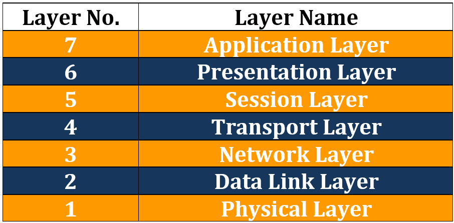
The more complex functions, which are closer to the user, are at the top, moving down to network cable specifications at the bottom layer. The ISO created the OSI model to help vendors agree on a set of common standards with which they could all work. This involved dividing network functions into a set of logical levels or layers. Each layer would perform a specific set of functions, so, for example, if your company wanted to focus on network firewalls, they would work with other vendors’ equipment.
The advantage was that each device was designed to perform a specific role well, rather than several roles inadequately. Customers could choose the best device for their solution without being tied to one vendor. Troubleshooting became much easier because certain errors could be traced to a certain OSI layer.
You can easily remember the names of the layers with the mnemonic “All People Seem To Need Data Processing” I would certainly get used to referring to each layer by its number because this is how real-world network technicians use the OSI.
As data is passed down from the top layers to the bottom for transportation across the physical network media, the data is placed into different types of logical data boxes. Although we often call these data boxes “packets,” they have different names depending upon the OSI layer. The process of data moving down the OSI model is referred to as encapsulation. Moving back up and having these boxes stripped of their data is called de-encapsulation.
Layer 1 – Physical Layer
At Physical Layer, frames are converted into bits for placing on the wire. These bits consist of electrical pulses, which are read as ON/OFF bits or binary 1s and 0s, respectively. Hubs work at this layer, and here is where you will find cable specifications, such as RJ45.
Layer 2 – Data Link Layer
The Data Link Layer chops down packets into smaller units referred to as frames. Layer 2 switches work at this layer and use hardware or MAC addresses, so they can switch traffic much faster because there is no need to check IP addresses and routing tables. WAN protocols work at Layer 2, including HDLC, ISDN, and PPP. Ethernet also works at Layer 2.
In order to interface with the upper and lower levels, the Data Link Layer is further subdivided into the Logical Link Control Sublayer and the Media Access Control Sublayer. The LLC Sublayer interfaces with the Network Layer and the MAC Sublayer interfaces with the Physical Layer.
Layer 3 – Network Layer
The Network Layer takes the segments from the Transport Layer and breaks them down into smaller units called packets. Most network engineers refer to data as packets, no matter what the OSI layer, which is fine; however, just remember that they are technically packets at the Network Layer.
The Network Layer must determine the best path to take from one network to another; for this reason, routers work at this layer. Routers use logical addressing here, and TCP/IP addressing is called IP addressing, which will be covered in detail later.
Layer 4 – Transport Layer
The role of the Transport Layer is to break down the data from the higher layers into smaller parts, which are referred to as segments (at this layer). Virtual circuits are set up here, which are required before devices can communicate.
Before the data can be passed across the network, the Transport Layer needs to establish how much data can be sent to the remote device. This will depend upon speed of the link from end to end. If you have a high-speed link but the end-user has a low-speed link, then the data will need to be sent in smaller chunks.
TCP operates at the Transport Layer of the OSI model. It provides a connection-oriented service for reliable transfer of data between network devices. TCP also provides flow control, sequencing, windowing, and error detection. It attaches a 32-bit header to the Application Layer data, which is in turn encapsulated in an IP header. TCP is described in RFC 793. Common TCP ports include the following:
| Popular Applications and Their Well-Known Port Numbers | ||
| Port Number | Protocol | Application |
| 20 / 21 | TCP | FTP (Data / Control) |
| 22 | TCP | SSH |
| 23 | TCP | Telnet |
| 25 | TCP | SMTP |
| 53 | UDP, | DNS |
| 67 / 68 | UDP | DHCP (Server / Client) |
| 69 | UDP | TFTP |
| 80 | TCP | HTTP |
| 110 | TCP | POP3 |
| 161 | UDP | SNMP |
| 443 | TCP | SSL |
| 514 | UDP | Syslog |
Layer 5 – Session Layer
The role of the Session Layer is to set up, manage, and terminate sessions or dialogues between devices. These take place over logical links, and what is really happening is the joining of two software applications. SQL, RPC, and NFS all work at the Session Layer.
Layer 6 – Presentation Layer
The Presentation Layer presents data to the Application Layer. Multimedia works here, so think MP4, JPEG, GIF, etc. Encryption, decryption, and data compression also take place at this layer.
Layer 7 – Application Layer
This layer is the closest layer to the end-user, you and me. The Application Layer isn’t the operating system of the devices but usually provides services such as e-mail SNMP/POP3, HTTP for web browsing, and file transfer services using FTP. The Application Layer determines resource availability.
Each of the above seven layers has some protocols associated with it. Below table lists the protocols at each layer:
| Layer No. | Layer Name | Protocols at each Layer |
| 7 | Application Layer | HTTP, SMTP, DHCP, FTP, Telnet, SNMP |
| 6 | Presentation Layer | TLS, SSL |
| 5 | Session Layer | PPTP, L2TP and NetBIOS |
| 4 | Transport Layer | Transmission Control Protocol (TCP), UDP, SCTP |
| 3 | Network Layer | Internet Protocol (IPv4), IPv6, IPX, AppleTalk, ICMP, IPSec and IGMP |
| 2 | Data Link Layer | ARP, HDLC, Ethernet, PPP, X-25, ATM |
| 1 | Physical Layer | Bluetooth, PON, OTN, DSL, Ethernet |
Using a layered approach can be very effective when you’re troubleshooting your network equipment. There is different equipment associated with each layer of OSI Model. The only decision from this point onwards is to determine which way you want to use the OSI stack – top-down, bottom-up, or divide-and-conquer method, which involves focusing on sections of the network in turn.
Many network devices must actually understand the protocols at multiple OSI layers, so the layer no. mentioned for each equipment actually refers to the highest layer that the device normally operates about when performing its core work. For example, routers need to think about Layer 3 concepts, but they must also support features at both Layers 1 and 2. Below table lists down the Network equipment which is associated with each layer:
| Layer No. | Layer Name | Equipment at each Layer |
| 7 | Application Layer | Gateways, Firewalls, all end devices like PC’s, Phones, Servers |
| 6 | Presentation Layer | Gateways, Firewalls, PC’s |
| 5 | Session Layer | Gateways, Firewalls, PC’s |
| 4 | Transport Layer | Gateways, Firewalls |
| 3 | Network Layer | Routers, Layer-3 Switches |
| 2 | Data Link Layer | Bridges, Modems, Network Cards, layer2 Switches |
| 1 | Physical Layer | Hubs, Repeaters, Cables, Optical Fiber, Wireless |
Good piece of concepts
I like your way of explanation. Nice & concise.
When is your new course of CCNA starting? can you share enrollment info?
1july
Good one … can you plz also share the TCP/IP Model in similar context?????
Thanks Sandra. TCP_IP is in progress. You will get auto-notification as soon as it is available in this week.
Nice sum up of concepts!!
Thanks Joseph. Please stay in touch for similar content updates.